Rope Terminations and Splicing
TTI provides a complete termination design service in all types of terminations
- Splicing
- Socketing
- Resin Socket
- Barrel & Spike
- Swaged Thimbles
TTI can provide design and engineering services as follows
- Termination selection
- Modeling mechanical and fatigue properties (see Dr. C.M. Leech paper on modeling terminations The analysis of splices used in large synthetic ropes)
- Specification of termination for engineered systems
- Problem solving and failure analysis
- Design of novel new terminations
The following notes are intended to give an overview of the main termination types used in fibre ropes. Knotting, which is also used, develops approximately 50% of the rope strength.
Splicing
Splicing is routinely carried out on Braided, 3 or 4 Strand Ropes and Wire Rope Constructions. The splice design must take into account the rope application. For example, the splice must not be a site for accelerated fatigue and must not loosen with rope rotation.
Classical named splice designs, such as Admiralty, Liverpool and Australian have proven over the centuries that they can be efficient but they were developed for application to natural and steel fibre ropes, and were recently adapted for synthetic fibre ropes.
There is no common formal process of ‘designing’ to determine the number of tucks, angles and dimensions, and there are no formal, independently monitored standards for designer qualifications. TTI has developed a splice model for the US Navy which includes contact pressure and slip modes and can be used to study mechanical properties of a splice.
Tests developed and conducted by TTI with miniature pressure transducers inserted between the spliced strands measured the radial pressure along the full length of a splice. The radial pressure trend along the splice length is shown below. Maximum pressure occurs at about the midpoint of the full tuck region and diminishes in each direction to a much lower value. From this we can deduce that there are three critical zones along the length of a splice:-
i) At the midpoint of the full tuck region and when the optimum contact pressure is provided by the correct splice design, the spliced strands should be locked under conditions of continuous cycling. (During the initial bedding-in, there may be a few slips while tensions equalise between the sub-ropes.)
ii) At each end of the splice, there are transitional zones where more slip occurs during bedding-in because the radial contact pressure is lower.
iii) Radial contact pressure continues to fall off in the taper region at a slower rate, thus it is essential to have a sufficiently long taper region otherwise tensile or fatigue failure can occur in the splice.
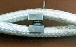
Measurements of inter-strand pressure in a splice
Pressure variation along length of splice
Another development by TTI is the methodology to determine the stability of the splice to prevent splice under varying cyclic load conditions. This technique can also be used to develop the optimum splice length. A graph below shows the slip between strands at various positions along the length. This shows that this particular splice would continue to slip with cycles and would eventually pull out.
Research by TTI has identified the key parameters that affect splice performance as follows
- Tuck pitch
- Number and length of full tucks
- Number and length of taper tucks
- Shape of tucks
- Eye angle
- Spool diameter (in eye)
- Spool groove shape
Case Study
1200tonne Kevlar spliceTTI has developed high tensile and fatigue efficienct splices for Parallel Yarn, wire rope construction and Parallel Strand Ropes. A typical example includes a novel splice in a 1200tonne break load Kevlar rope that was only 1.5m long compared to the industry standard method 4m long. This was achieved by splicing within the strand, rather than splicing through the rope. The findings from the research and tests developed by TTI over the years and computer modeling were instrumental in the ability to develop this splice in such a short length.
Socketing
Wire rope sockets can be used to good effect on fibre ropes. Generally they are filled with a 2 component cold cure polyester resin. It is important to ensure that the rope yarns are evenly distributed in the socket and that they are thoroughly wetted by the resin.
Barrel & Spike
The barrel & spike is often used with parallel yarn constructions. It uses the wedge action of the spike against the fibres and the body of the barrel to develop holding power. Typically, the included angle of the barrel interior cone is 6o. As with the resin socket, it is vital to ensure the the yarns are straight on the spike and are evenly distributed round it.
Case Study
Nick O’Hear (Technical Director TTI) designed the barrel and spike terminations for the Colserolla Tower in Barcelona.
The upper section of the tower was guyed with 56 mm diameter parallel fibre aramid ropes with a break strength of 200 tonnes. Each stay consisted of a group of 7 ropes giving a combined strength of 1,400 tonnes.
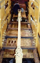
The termination design was subject to finite element analysis and the FEA results were checked by tensile testing and strain gauge measurements. The test results confirmed the location of high stress and validated both the design and the FEA analysis.Resin was used on the fibres in the termination to reduce internal abrasion and to guarantee that the fibres could not pull out. Repeat load testing demonstrated that the fibres were locked in the termination and over 10 years in service has further proved the reliability of the system.

Collserola TowerSwaging
Swaging is an effective method of terminating small fibre ropes. Generally the swaging system is that used for steel which can cut through the fibre. To avoid excessive pressure, the swaging die used is one size too large or the swaging thimble is one size too big. To avoid slip, generally 4 thimbles are used. With some experimentation very high strengths can be obtained on small ropes.
Marine Rope Termination & splicing
Services
Design
Ropes
Riser protection nets and other marine systems
Rope Terminations and Splicing
Electro-mechanical CablesTesting
Yarn Abrasion and Friction Testing
Textile Testing
NDT (Non Destructive Testing)
Technical Inspection ServicesJIP and R&D
Failure Analysis
Software development
Textile Solutions
Mooring
Expert Witness
People
Stephen J Banfield
Denise l Banfield
Chris Berryman
Kevin Black
Nigel Briggs
Martin Delaney
Jack Evans
Jim Evans
Mark Evans
John F Flory
Animesh Garg
Roger E Hobbs
James Mackay
Tom Mackay
Ross Morley
Fanggang NING
Nick O'Hear
Alan T Ractliffe
Isabel Ridge
Xavier Wadbled
Pengzhu Wang
Sam Weller
Ben Yeats
About TTI
Contact
TTI - How We Give Back
Cordage Institute Certificate - Member for over 30 years.
Clients & Affiliates
**Typical contracts and services
TTI has completed since 1998
© Copyright 2003-2025 TTI Ltd. All rights reserved. Web design by BarkWeb
Contact | Site Map | External Privacy Policy | Refund policy | Delivery policy | Quality PolicyTension Technology International Ltd and its subsidiary companies are committed to ensuring there are fair working practices policies in place including those relating to diversity, gender, real living wage and effective individual voice conditions. Within the United Kingdom we are also committed to devolved fair work policies (e.g. Fair Work First Policy) as they apply appropriately to the location of TTI registered companies.
/NQA-ISO-9001-Logo-UKAS.jpg)
/NQA-ISO-45001-Logo-UKAS.jpg)