Computer Modelling of Large, High-Performance Fibre Rope Properties
Stephen J. Banfield and John F. Flory
Presented at Oceans '95, San Diego, October 9-12, 1995
Abstract
Rope development has historically involved building a prototype rope, testing it to determine performance, and then building another rope in an attempt to improve that performance. This empirical method was affordable with small conventional ropes. Interest is now focused on developing very large ropes made of polyester and high-modulus materials such as aramid. For such ropes, the empirical method is too expensive and too time consuming.
The use of rope computer models can greatly reduce rope development costs. Parameters such as fibre properties and component arrangements can be studied to determine a near-optimum design before making and testing a prototype rope. Test results can be used to calibrate the computer model, and additional modelling can then be conducted to improve rope properties or predict rope performance under other conditions.
This paper presents several examples. A study predicted how a slight change in strand lay length can significantly improve rope cyclic load fatigue life. Modelling of hysteresis heating helped plan a laboratory test program and complemented the testing by extrapolating the measured results to larger ropes and other test conditions.
Table of Contents
Introduction
Prototype Rope Testing Is Costly
Computer Modelling Can Cut Costs
The Rope Computer Model
Description of the rope model
Hierarchical Element Structures
Rope Structures of Interest
Modelling of Stress/Strain Relationship
Accounting for Deformation Modes
Modelling of Rope Failure
Modelling of Rope Fatigue
Examples of use of program
Fatigue Modelling
Effects of Strand Lay Length on Strength and Fatigue
Hysteresis Heating Studies
Conclusions
ReferencesIntroduction
Prototype Rope Testing Is Costly
Developing a new rope product and qualifying it for critical service applications can be expensive. This was not the case when rope material was inexpensive, rope making was simple, and applications were undemanding. But now there is interest in using high-performance fibres in ropes over 100 mm (4 in.) diameter, with break strengths exceeding 1,000 tons, in very demanding marine applications with expected lives of ten years or more.
For such applications it is simply not possible to build and test a full-scale rope in situ on a non-critical test facility to prove that it works ! that would take ten years or more, and by that time the rope product would probably be obsolete. The cost would also be prohibitive.
Laboratory testing can provide some of the answers. However even that can be very expensive. In a recent aramid rope test program, the fourteen rope specimens had a value of about $60,000. Three break tests and eleven cyclic load tests cost over $100,000. There were also technical support and administration costs. Testing accomplished a total of only about 100,000 load cycles. equivalent to about 70 days of marine service at a 1 min. cycle period.
Computer Modelling Can Cut Costs
What if much of the prototype rope making and testing process could be simulated on a computer? It is now possible to predict break strength, load/extension, torque/twist, and even the cyclic load performance of a rope by using a computer program model.
Before making a prototype rope, such a program can help to predict and to optimize the performance by investigating possible effects of altering fibre properties and rope making parameters. With test data from a prototype made to that computer rope design, the program can be "calibrated" and then used to further optimise the performance with a high degree of confidence.
Such a program can also supplement cyclic load testing. With knowledge of fundamental failure mechanisms and the cycles to failure or residual strength performance from laboratory or field testing, the program can then predict how changes in fibre properties and rope making parameters can alter the rope's performance.
The computer program can also expand on the results of cyclic load testing, eliminating the need for extensive testing. The program can be used to predict the rope cycles to failure at other load ranges and residual strengths after various numbers of load cycles. It can also predict the potential performance of alternate rope designs which are similar to the tested design.
The Rope Computer Model
This paper briefly describes OpTTIrope, a rope computer model program which is capable of performing these tasks. It gives several examples of how the program has been used to improve rope designs and to complement rope testing.
The basic concept for the program was conceived and demonstrated by Dr. Chris Leech. (Ref 1, Ref 2)
Dr. Leech and others of Tension Technology International (TTI) further developed the program as "GenRope" under a contract for the U.S. Navy Civil Engineering Laboratory. (Ref 3, Ref 4, Ref 5)
TTI is now expanding and enhancing the program, which is now known as "OpTTIrope". (Ref 6, Ref 7, Ref 8)
Description of the rope model
Hierarchical Element Structures
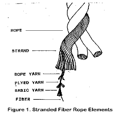
Figure 1 shows the manner in which a typical fibre rope is assembled. Basic yarns are twisted together to produce a rope yarn, a number of rope yarns are arranged in helical layers to produce a rope strand, and groups of strands are laid together to form the finished rope.

The computer program models the rope structure in a hierarchical fashion, much the same as the actual rope making process.
The modelling process begins by describing a basic element, such as the fibre yarn. Input data include the basic element properties ! density, size, load-extension, break strength, friction and, optionally, appropriate coefficients for creep, internal abrasion, axial compression, and hysteresis.
The manner in which this basic element is assembled into the next hierarchical level is then described ! number of elements, degree of twist, and possibly variation of tensions. The assembly of that next element to form the following hierarchical level is then described, etc.
Within each structural level, e.g. the strand, the next lower element, e.g. the rope yarn, follows a helical path about the central axis of that level. The geometric path description of the lower level elements can become very complex. Even with a complete geometric path description, it would be virtually impossible to directly calculate the properties of the highest level from those of the lowest level for such a complex fibre rope structure.
However within the rope model, the calculation of properties proceeds in steps. Starting from the known properties of the basic element, the properties of the next structural level are calculated from the known properties of the elements which make up that structural level and the processes used in making up that level, e.g. twist, packing factor, and tension balance. Those higher-element properties are then used in turn as input to calculate the properties of the next structure level, and so on, until the properties of the entire rope are known.
Rope Structures of Interest
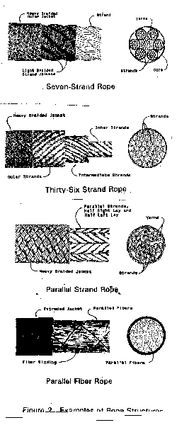
Figure 2 illustrates several typical rope structures which can now be modelled using the computer program.

One familiar high-performance rope is the helical-path-strand structure, comprised of strands which are laid together in a helical pattern. The term laid indicates that the individual strands revolve in a planetary pattern instead of simply being twisted together when forming the rope.
The seven-strand structure is commonly used for large size polyester ropes and medium size HMPE and aramid ropes. It may have a non-load-carrying core and then be called a six-strand rope.
The thirty-six-strand structure is used in very large aramid ropes; it is sometimes called "wire rope construction". Other examples of this form are eighteen-strand ropes and even three- and four-strand ropes.
Another structure is the parallel-strand rope, also used for large nylon and polyester ropes and medium and large HMPE and aramid ropes. Many strands are arranged in parallel and covered with a jacket. These strands are essentially three-strand ropes, and thus they are sometimes referred to as "sub ropes". The jacket provides the unification otherwise accomplished by twisting (laying) or braiding of the strands.
A further application of this parallel-element principal is the parallel-fibre rope. Here many fibres or yarns are assembled in axial alignment and encased within a tight jacket or cover.
The rope computer model can handle any of these rope structures. The manner in which the helical-path-strand structure is modeled was described above. The individual strands or "sub ropes" of the parallel-strand rope are also modelled in this manner. Then statistical variations of the breaking strains and the relative lengths of the individual strands are accounted for, applying a factor for the degree of unification and compaction accomplished by the cover. The parallel fibre rope is treated only as a statistical model, accounting for variations in breaking extension and relative lengths and applying a jacket unification and compaction factor.
The computer program can now model some of the aspects of the splice at the end of a helical-path-strand rope. This portion of the model can be expanded to model some forms of braided rope.
Modelling of Stress/Strain Relationship
With appropriate modelling of the rope structure, described above, it is then necessary to relate the tensions, extensions, torques and twists applied to the entire rope structure to those imposed on the individual rope elements. This is done through the Principal of Virtual Work :
This means that work performed by tension P changing the rope length L plus work performed by torque T changing the rope twist 2 is equal to the overall work U performed on all elements of that rope.
Prescribed changes in length and twist are applied to the most major structural element, that is the rope. From the rope structural model, the resulting changes in length and twist on the next lower structural level are calculated. And from those changes, the succeeding lower level changes are calculated, until the resulting change in length (stress) on the lowest structural level or basic element is known. (Torque/twist properties of the basic element can be input if known.)
The tension in the basic element which corresponds to this imposed change in length is calculated. Tensions and torques on each of the succeeding hierarchical elements are then calculated to determine the corresponding tension and torque on the rope itself.
Accounting for Deformation Modes
Of fundamental importance in modelling fibre ropes are the many possible deformation modes.
The various structural levels can compress and change in shape. The resulting changes in diameter then alter the helical paths of succeeding levels and thus change other important properties.
The various elements can slip relative to each other. The degree of inter-element movement depends on the tension on an element, the pressure between elements, and the coefficient of friction. As a result of slippage, the balance of tensions between elements is changed, abrasion damage may be produced, and heat may be released.
Modelling of Rope Failure
In an ideal rope structure, all of the elements share load equally such that they all reach rupture strain at the same time. In an actual rope, load sharing varies among elements due to many factors, including: unequal tensions applied during the rope making process, differences among lengths along various helical paths, non-linear stress-strain characteristics of synthetic material fibres, statistical variations of stress-strain and strain-to-rupture characteristics, compaction of elements, and slippage among elements.
The rope computer model program calculates and monitors the strains in all elements throughout the rope. It accounts for all of the important aspects mentioned above. Thus the program is able to predict which element will reach breaking strain and fail first and at what imposed rope strain or torque that element failure will occur.
The program then models the cessation of load-carrying ability of that element and transfers that load to adjacent elements. The program establishes the changes in strain in those adjacent elements and the resulting change in overall rope length. In some cases, the failure of one or several elements will cause the adjacent elements to fail immediately, possibly leading to catastrophic failure of the entire rope. In other cases, the rope does not fail but nevertheless suffers a loss in strength.
Modelling of Rope Fatigue
The rope computer program can also simulate cyclic tension fatigue. In this mode it is essential that the strength degradation mechanisms be adequately represented. The abilities of the program to model the effects of creep and hysteresis heating have been demonstrated against laboratory test results. The coefficients to represent internal abrasion and axial compression are established for most fibres of interest, but the program has not been extensively verified with test results in these modes.
Laboratory tests on yarns or detailed examination of yarns taken from ropes with known histories may be needed to establish the appropriate rate of abrasion wear. The buildup of heat within a rope comes from hysteresis effects within the fibre material (Tan *) and from friction between elements.
At present, the fatigue model can best be employed in conjunction with results of well-controlled laboratory cyclic load tests. Detailed examination of the test specimen can provide estimates of the relative importance of the above mentioned effects on fatigue life.
The appropriate coefficients can be input and adjusted so that the model predicts the same performance. These coefficients can then be changed in the model to help predict how such property changes might affect actual rope performance. The rope computer program can also be employed to investigate the effects of changes in rope-making parameters, such as twists and tensions, on fatigue life.
Another potential use of the program is to supplement the results of a few cyclic load tests in order to predict performance under different test conditions. Once the model is calibrated to predict the results of cyclic load tests at one load range or one peak load, the program can then predict with a fair degree of confidence the cyclic load performance at other load ranges or peaks and even at randomly varying loads.
The program may also be used to investigate the scale effects of rope size. It may be possible to estimate the fatigue performance of a very large rope, e.g. 100 mm dia. from carefully controlled and monitored testing of smaller, e.g. 50 mm dia. rope. In order to accomplish this, the rope model must account for effects which may be more pronounced in the large rope than in the small rope, for example, internal pressures and temperatures and their possible influences on creep and abrasion.
Examples of use of program
Fatigue Modelling
Tension-tension cycling of fiber ropes can produce four modes of fatigue: creep, internal abrasion, hysteresis and axial compression. The advantage of computer modelling is that any combination of these fatigue modes can be implemented, appropriate to the application service conditions.

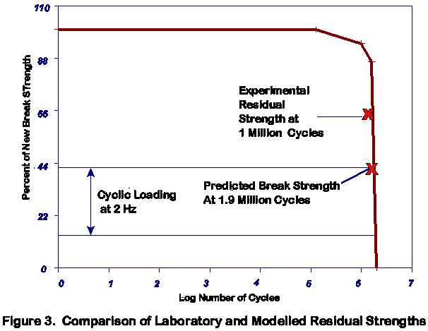
Figure 3 presents the predicted residual strength against applied cycles for one such test. This is for a 5 ton aramid rope cycled at 2 Hz between 14% & 42% of its predicted new breaking strength. The progressive reduction of break load accounts for the effects of creep rupture, hysteresis heating and abrasion damage. The experimental point depicts the residual strength of a rope which was loaded to break after it had survived 1 million cycles
Effects of Strand Lay Length on Strength and Fatigue
The computer model has been used to investigate the effects of strand lay length on the break strength and fatigue life of a large aramid rope. The rope which was modelled is a 6+12+18=36 strand aramid rope. The lay length of each strand layer can be chosen in order to maintain a constant helix angle across all layers.
In theory, this constant-helix-angle structure should give equal load sharing across all strand layers in the rope. But theory does not account for rope dilation ! that is the change in cross sectional area due to Poisson’s ratio and wedging of strands that are transversely soft. This rope dilation reduces the radius and alters the helix angle of each layer and thus affects the load sharing among the strands.
Traditional rope design theory is not adequate when so many variables must be considered, not only because they affect static properties but also because they affect fatigue life. Computer modelling can properly represent this rope dilation and its potential effects on rope fatigue life.

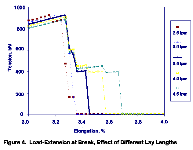
Figure 4 is the static load extension curve generated by the computer for this 36-strand aramid rope. It shows that portion of data for the break between 3 and 4% extension. The figure shows data for five different lay lengths, expressed in terms of pitch from 2.5 to 4.5 tpm (turns per meter), in the outer 18-strand layer of the rope.
The modulus, as indicated by stress at 3% extension, decreases by 10% when the pitch increases from 2.5 to 4.5 tpm. Changing outer layer pitch from 2.5 tpm to 3.5 tpm increases break strain by about 5% and increases peak load by about 1%. But a further change to 4.5 tpm reduces break strength by about 5%, with little change in break strain. The optimal new break strength is achieved when the principal load bearing components break together, and this is achieved at an outer layer pitch of approximately 3.5 tpm.
The computer program was also used to predict the cyclic tension fatigue for each of these ropes. The rope with 3.5 tpm outer layer pitch, which produced only a 1% improvement in break load, exhibited an 18% increase in fatigue life.
The computer program results indicate that such large aramid ropes achieve only about 40% of the aggregate fibre strength. This indicates that significant improvements in break strength and fatigue life might be achieved by using computer studies.
Hysteresis Heating Studies
Norsk Hydro are impressed by the potential cost and technical advantages of fibre ropes over steel ropes for deepwater mooring of production and drill ships, and even large platforms. Several rope and system design criteria need further investigation before such a mooring could be deployed. One question is ! What is the magnitude of heat build up and time taken to reach equilibrium due to hysteresis heating in large polyester ropes in the 100 year storm condition?
This hysteresis problem was investigated for Norsk Hydro using the OpTTIrope computer model. In preparation for a laboratory test program, a scale rope of 100 mm diameter 250 ton break load was modelled. As shown in the Table, at a strain amplitude of 0.25%, the program predicted a temperature rise of 1EC over ambient.
Mean Cyclic Load
% of Break LoadStrain Amplitude % Temperature Rise degreeC 20 % 1.0 % 6° 0.5 % 3° 0.25 % 1° Modelled Temperature Rise, 100mm polyester rope, 48 hrs cycling at 13 sec. period
This modelling was used to select the rope specimen size for laboratory tests. The thermocouples have only a 1°C resolution, and the rope specimen had to be large enough to produce that temperature rise. The laboratory temperature measurements agreed well with the modelled predictions. There was also good agreement on the time to reach thermal equilibrium.
The investigation showed that thermal equilibrium is reached in less time than the expected duration of peak storm conditions. This means that the temperature rise may have an upper limit. However, the time to reach thermal equilibrium for larger ropes will be longer. The heat transfer coefficients can be "calibrated" against the laboratory test results and then can be used to predict the upper temperature limit for various size ropes.
The ropes required to moor a production platform will require a break strength of about 1500 ton and be about 250 mm diameter. The model shows that hysteresis heating increases approximately proportional to the square of rope diameter. Preliminary modelling of these full size ropes, for the given conditions of a large platform in deepwater, shows that temperature rise may not be detrimental to the long term performance of polyester fibre rope.
Remaining questions are ! What effect does temperature have on long term performance and thus what is the safe maximum working temperature? High temperature, especially in the presence of water, may degrade the marine finish placed on fibres to prevent internal abrasion. Loss of the protective qualities of this marine finish could significantly decrease rope fatigue life.
Conclusion
Computer modelling of fibre ropes has many applications:
- basic rope design, e.g. parametric studies to improve properties,
- quality assurance, e.g. assessing the effects of deviations from design parameters,
- laboratory testing, e.g. investigating experimental variables to plan tests, and extrapolating test results to other circumstances,
- field applications, e.g. predicting rope static and fatigue properties in large ropes in actual service, and monitoring rope performance during service.
The OpTTIrope rope computer model program has been used in studies of rope breaking strength and extension, rope fatigue performance, and hysteresis heating effects. It has been used on helical-path-strand (e.g. "wire rope construction), parallel strand, and parallel fibre ropes, and it can readily be adapted for some braided rope constructions.
As new applications for high-performance synthetic fibre ropes are found, new and improved rope designs and additional property and performance data are required. Computer modelling can reduce rope development lead time and cost, from concept to prototype manufacturing through laboratory testing, and then to field installation and service.
Acknowledgements
The U.S. Navy supported the development of the GEN-ROPE program and related laboratory studies. Norsk Hydro supported the hysteresis heating study.
(July, 1999)
References
1. Leech, C.M. "The Assembly and Modelling of Synthetic Ropes using Microcomputers", Microcomputers in Engineering, Pineridge Press, Swansea, UK, 1986.
2. Leech, C.M., "Theoretical and Numerical Methods for the Modelling of Synthetic Ropes", Communications in Applied Numerical Methods, John Wiley & Sons, NY, vol. 3, 1987.
3. "Mathematical Models of Parallel and Twisted Synthetic Fibre Ropes under Static Loading", TTI Report for US Navy, NCEL, 1989.
4. Leech, C.M., "Aspects of Modelling of Synthetic Fibre Ropes", Marine Technology Conference '90 Proceedings, Marine Technology Society, Washington, DC, 1990.
5. Burgoyne, C.J., and J.F. Flory, "Length Effects Due to Yarn Variability in Parallel-Lay Ropes", Marine Technology Conference '90 Proceedings, Marine Technology Society, Washington, DC, 1990.
6. Leech, C.M., J.W.S. Hearle, M.S. Overington, and S.J. Banfield, "Modelling Tension and Torque Properties of Fibre Ropes and Splices", Third International Offshore and Polar Engineering Conference, Singapore, ISOPE, Golden, CO, 1993.
7. Hearle, J.W.S., M.R. Parsey, M.S. Overington, and S.J. Banfield, "Modelling the Long-Term Fatigue Performance of Fibre Ropes", Third International Offshore and Polar Engineering Conference, Singapore, ISOPE, Golden, CO, 1993.
8. Hearle, J.W.S, R.E. Hobbs, M.S. Overington, and S.J. Banfield, "Modelling Axial Compression Fatigue in Fibre Ropes", Fifth International Offshore and Polar Engineering Conference, The Hague, ISOPE, Golden, CO, 1995.
Fibre Rope Modeler papers
YOU ARE IN PAPERS

/NQA-ISO-9001-Logo-UKAS.jpg)
/NQA-ISO-45001-Logo-UKAS.jpg)
